Items tagged with Video
 Resource - Video
Design Automation
See how Solid Edge Design Automation can allow you to create shortcuts within Solid Edge to quickly accomplish common or repetitive tasks.
 Resource - Video
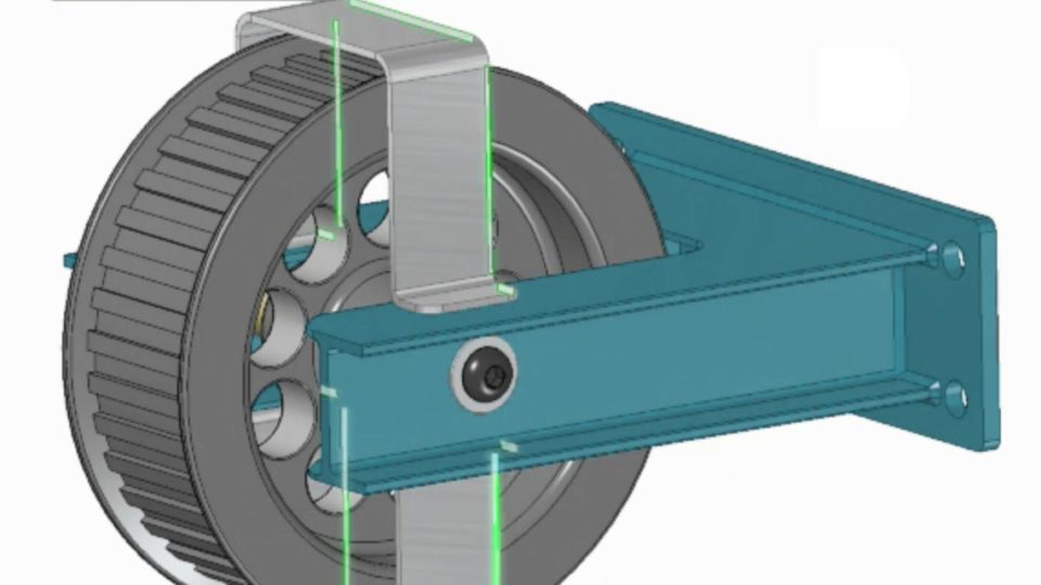
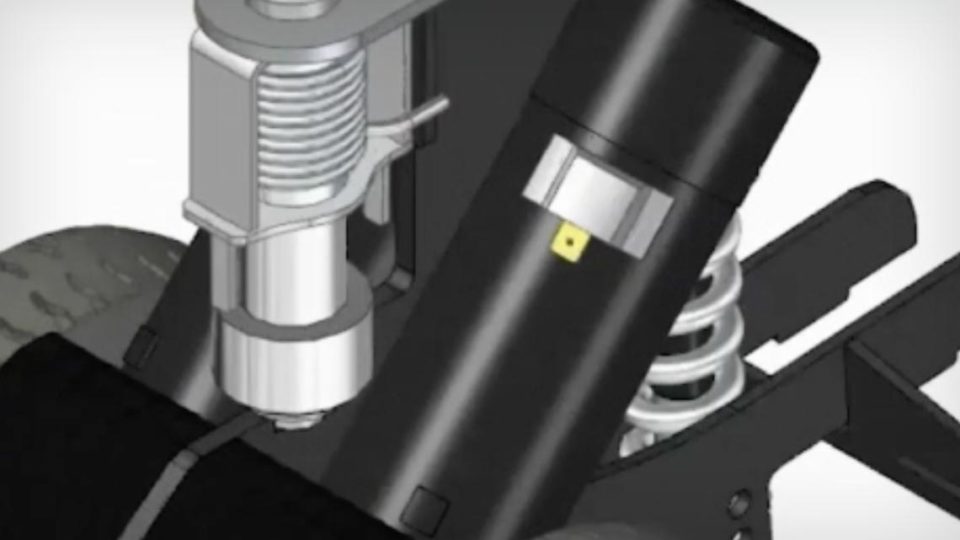
Simulation Preparation
Solid Edge simulation preparation provides easy-to-use tools for finite element analysis (FEA), regardless of the tool your design was created in.
 Resource - Video
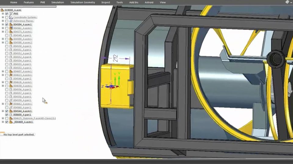
Simultaneous Editing Multiple Parts in an Assembly
Solid Edge synchronous technology allows for easy and quick simultaneous editing of multiple parts in an assembly. Learn more with this video.
 Resource - Video
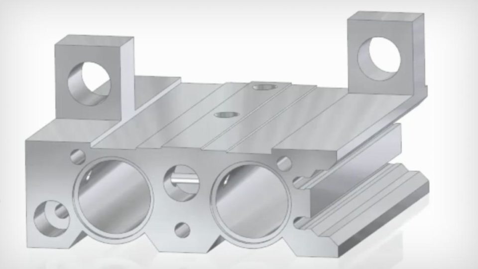
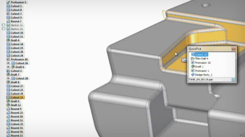
Editing Imported 3D Data
See how Solid Edge allows you to import data from any source, including other platforms, and start making edits and adjustments right away.
 Resource - Video
Design Intent Recognition
The Solid Edge Design Intent and the Advanced Design Intent panels are the two tools that together reveal the true power of synchronous technology.
 Resource - Video
Quick response to late-stage design changes
When a late-stage design change stands between you and a deadline, Solid Edge synchronous technology allows you to quickly and easily make requested edits.
 Resource - Video
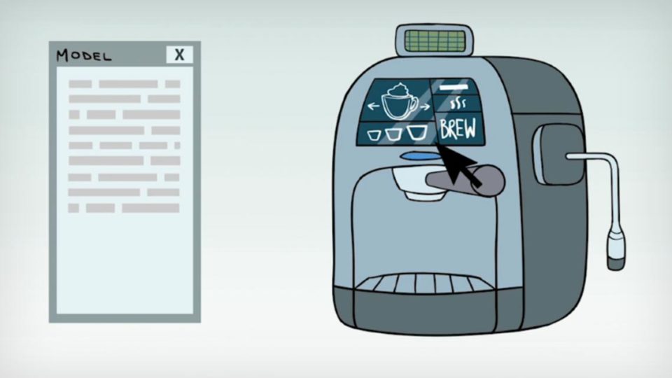
The Latest in Intuitive Design
Solid Edge 2019 from Siemens provides next generation product development for today’s engineers – learn more about the various tools and how they can help.
 Resource - Video
Faster, easier 3D models with Synchronous Technology
Get industry-leading part and assembly modeling tools and remove the constraints of traditional CAD with synchronous technology with Solid Edge.
 Resource - Video
Reverse Engineering: from 3D Scanning to CAD
In this demonstration, we show you how reverse engineering in Solid Edge allows you to expand your 3D design capabilities beyond the norm.
 Resource - Video
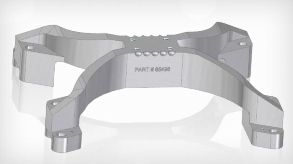
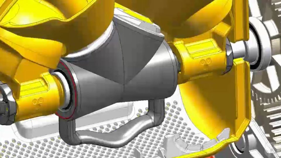
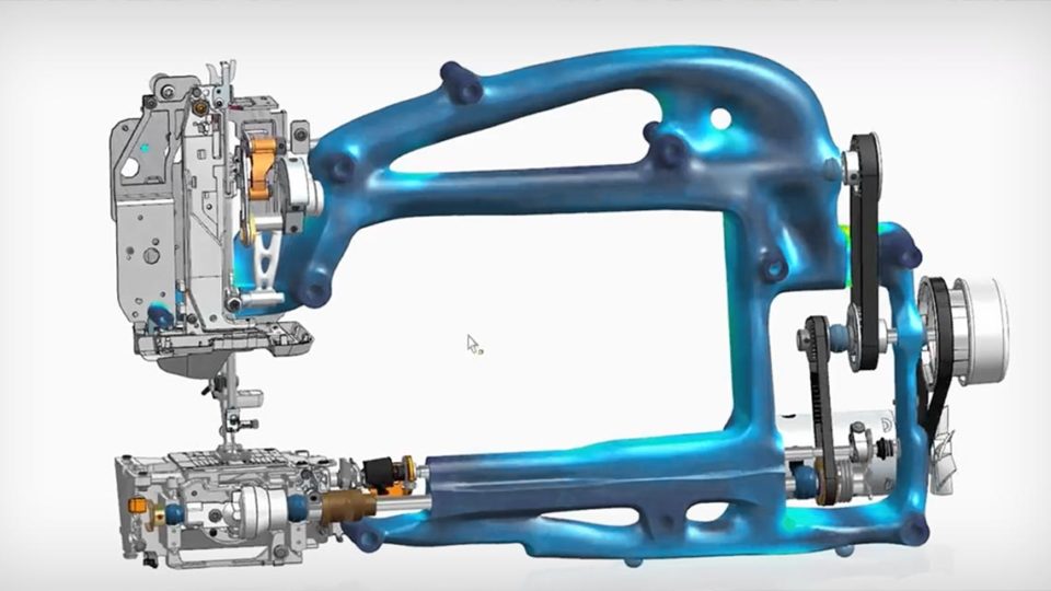
Generative design brings topology optimization
Generative design produces an organic, reduced-mass solution optimized within a defined space, accounting for permissible loads and constraints.
 Resource - Video
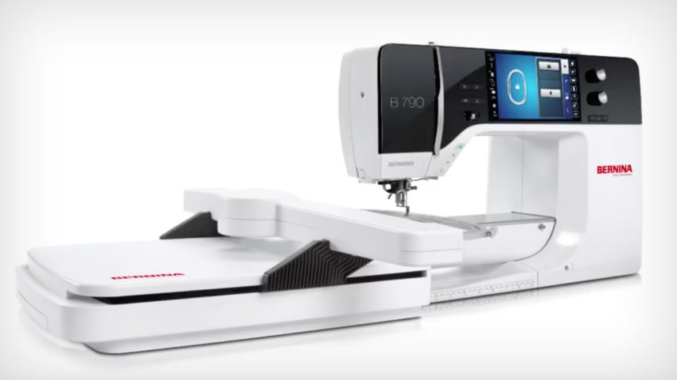
Next Generation Product Development Portfolio
See our next-generation product development portfolio. Electrical capabilities now integrated include wiring, harness and PCB design tools.
 Resource - Video
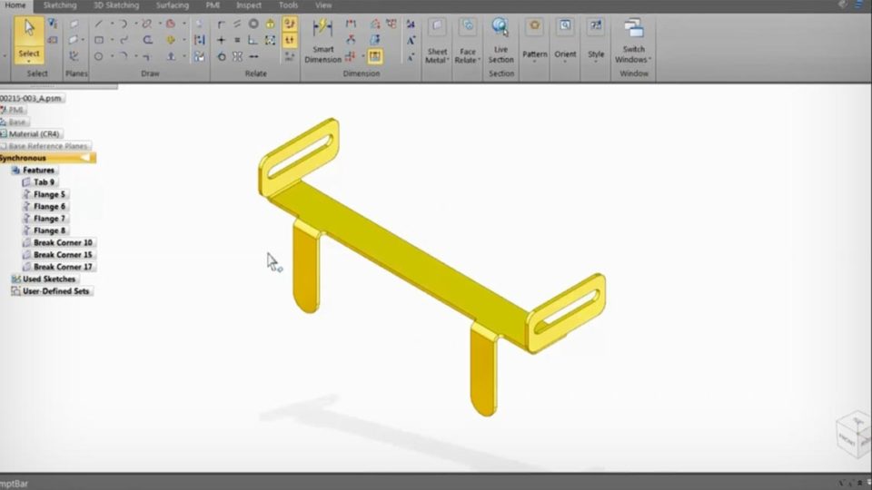
Design a sheet metal part
Effortlessly create sheet metal models from 2D sketches and work directly with geometry using Solid Edge’s cutting-edge sheet metal design features.
 Resource - Video
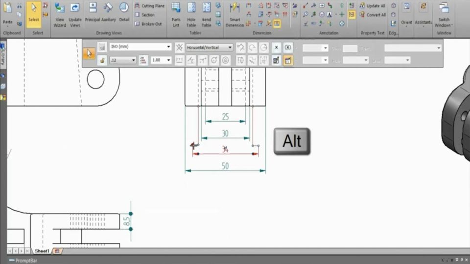
Create a detailed 3D drawing
With this video, see how Solid Edge makes it easy to turn CAD drawings into beautiful 3D designs to clearly convey the design idea.
 Resource - Video
Create a top-down assembly
Solid Edge offers two options for assembly designing and layout: top-down design and bottom-up design. See the differences with our informative video.
Resource - Video
Import and edit 3D data
Today we work in a multi-CAD world with a challenge to import and edit data from other platforms. See how Solid Edge can utilize data regardless of source.