Capabilities
High-performance assembly modeling and management
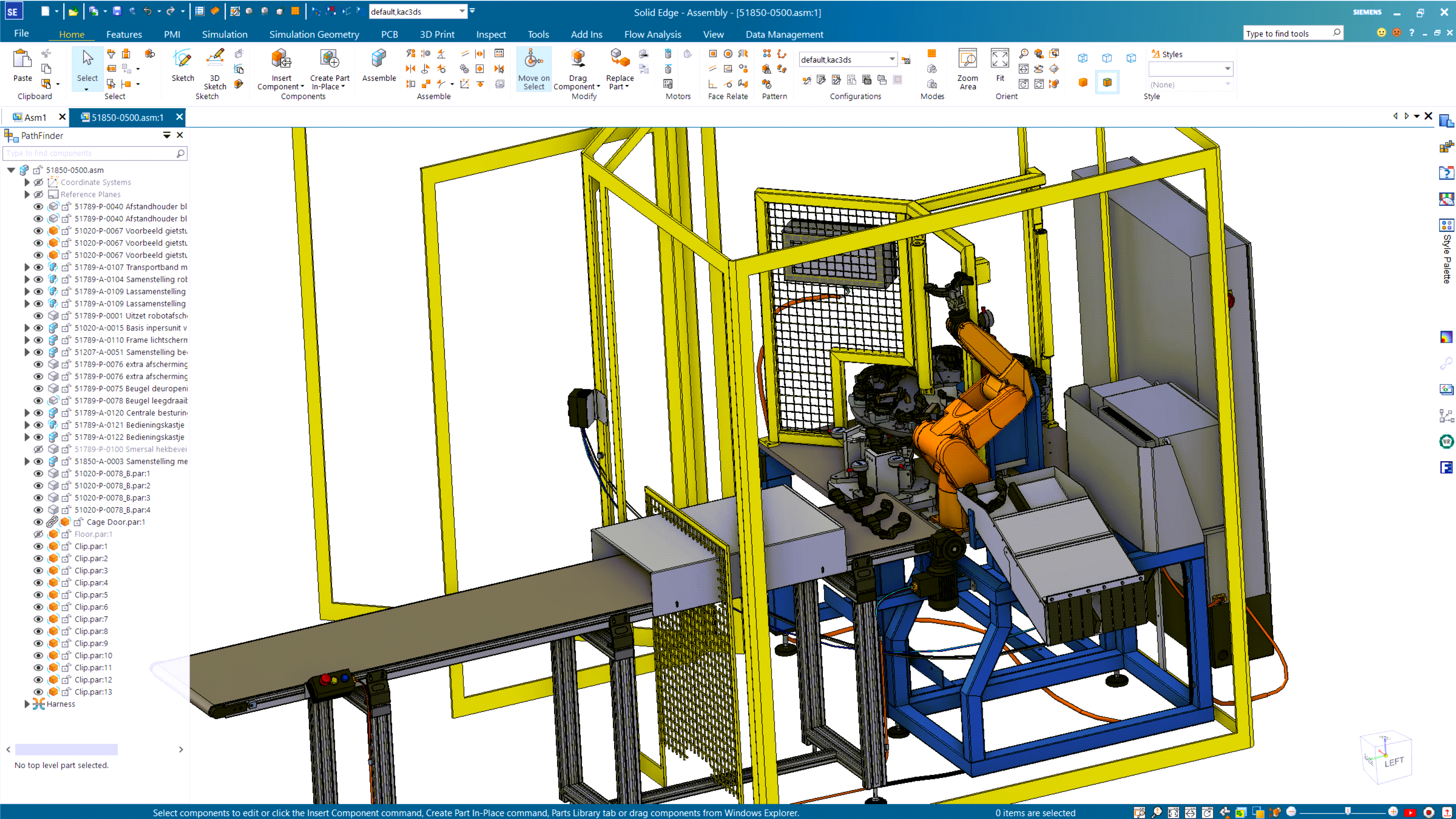
Designcenter Solid Edge enables you to create and manage large assemblies without sacrificing performance.
Unparalleled performance for large assemblies
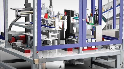
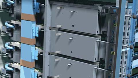
Solid Edge’s advanced memory management techniques allow you to easily manage assembly modeling. Quickly create, load and make updates to large assemblies and their associated drawings. Simplification of assemblies, definition of assembly zones, and structure-only navigation free up system memory and allow your graphics display to work more efficiently. With assembly modeling in Solid Edge, you can position complex subassemblies within master assemblies, and switch between simplified and detail views at will, without any waiting. Or quickly turn sub-assemblies into standalone parts, creating a placeholder component for improved performance. A high-performance mode for large assemblies, which automatically activates as an assembly grows, improves interactive performance, with gains of up to 10x faster workflows. Assembly preview allows users to enter a preview mode in order to reduce the amount of data that is loaded.
Visualize designs in the context of real-world environments
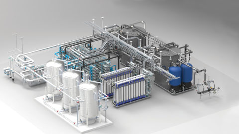
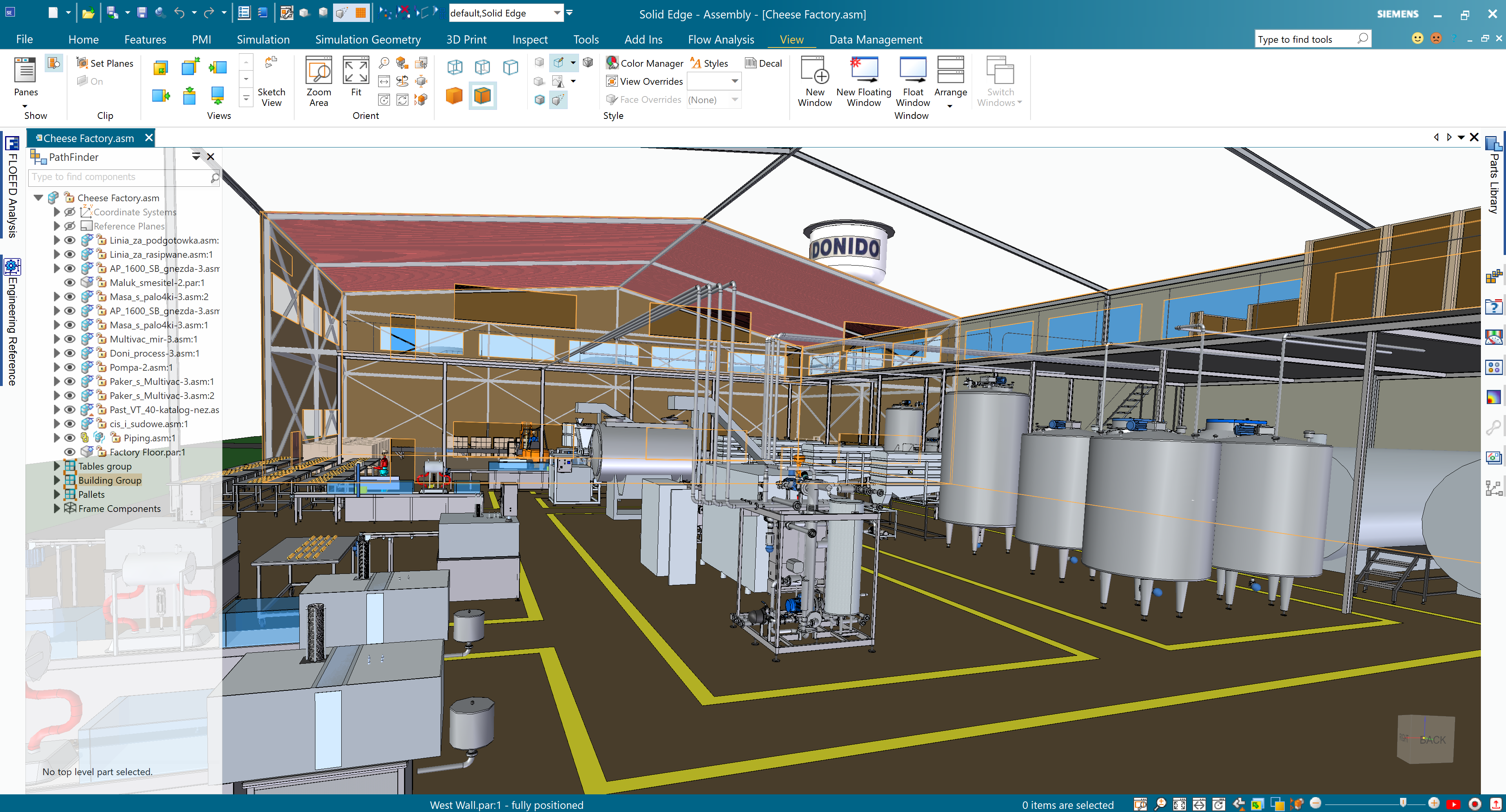
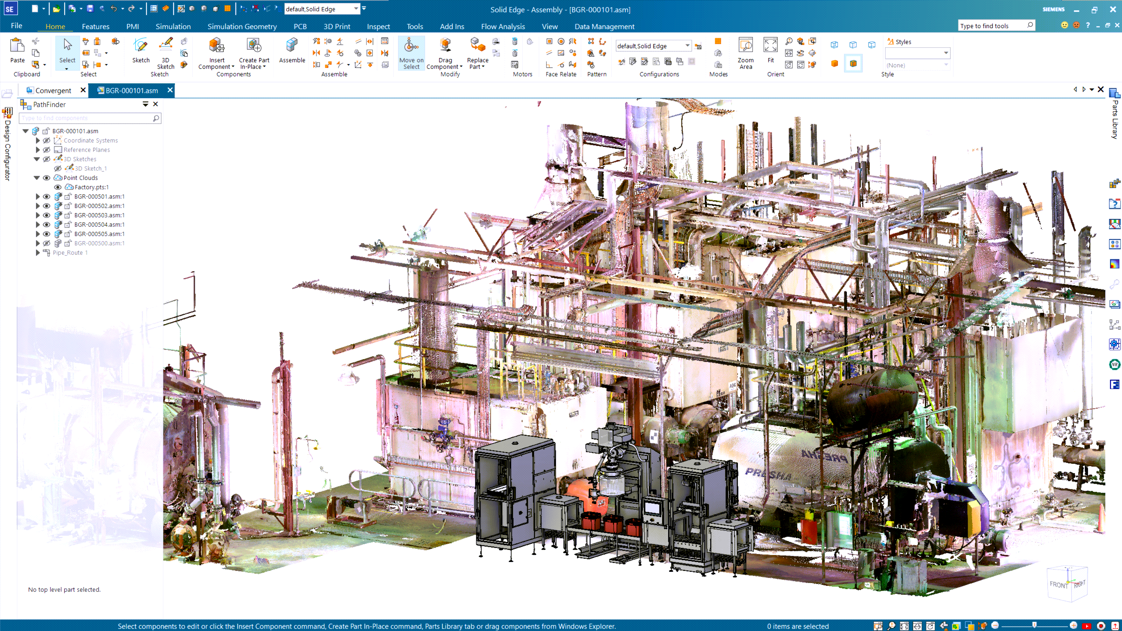
Full-color point cloud visualization for assemblies provides the confidence you need to position new design equipment in any setting, which is especially useful when retrofitting factories or plants. Solid Edge assembly measurement and viewing tools can be used to position and design equipment in the context of the point clouds.
Bottom-up and top-down modeling in context
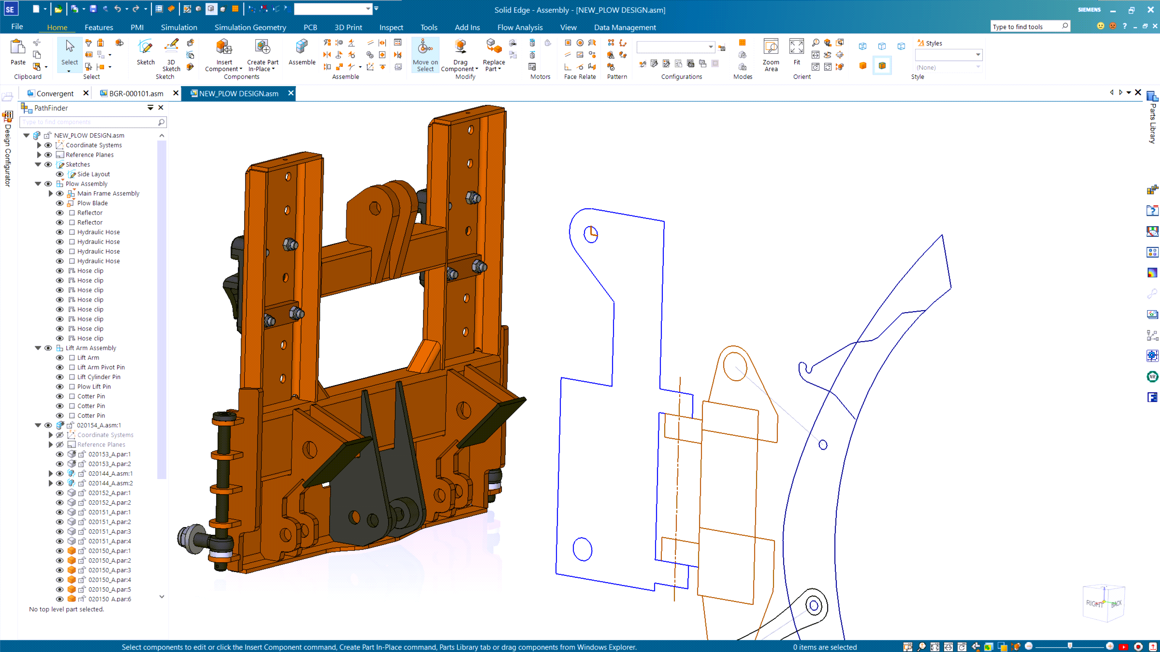
With Solid Edge, you can design the way you want to, whether bottom-up (by assembling existing components), or top-down (starting from a conceptual layout or by designing parts to fit into an existing assembly). A suite of assembly modeling commands and tools lets you use either approach associatively or non-associatively. Solid Edge’s unique synchronous technology helps you create and modify assemblies faster, using Boolean functions or simultaneous multi-part edits. No matter how your design begins, with Solid Edge you can work in the context of your assembly when creating or modifying components.
Easily manage assembly relationships
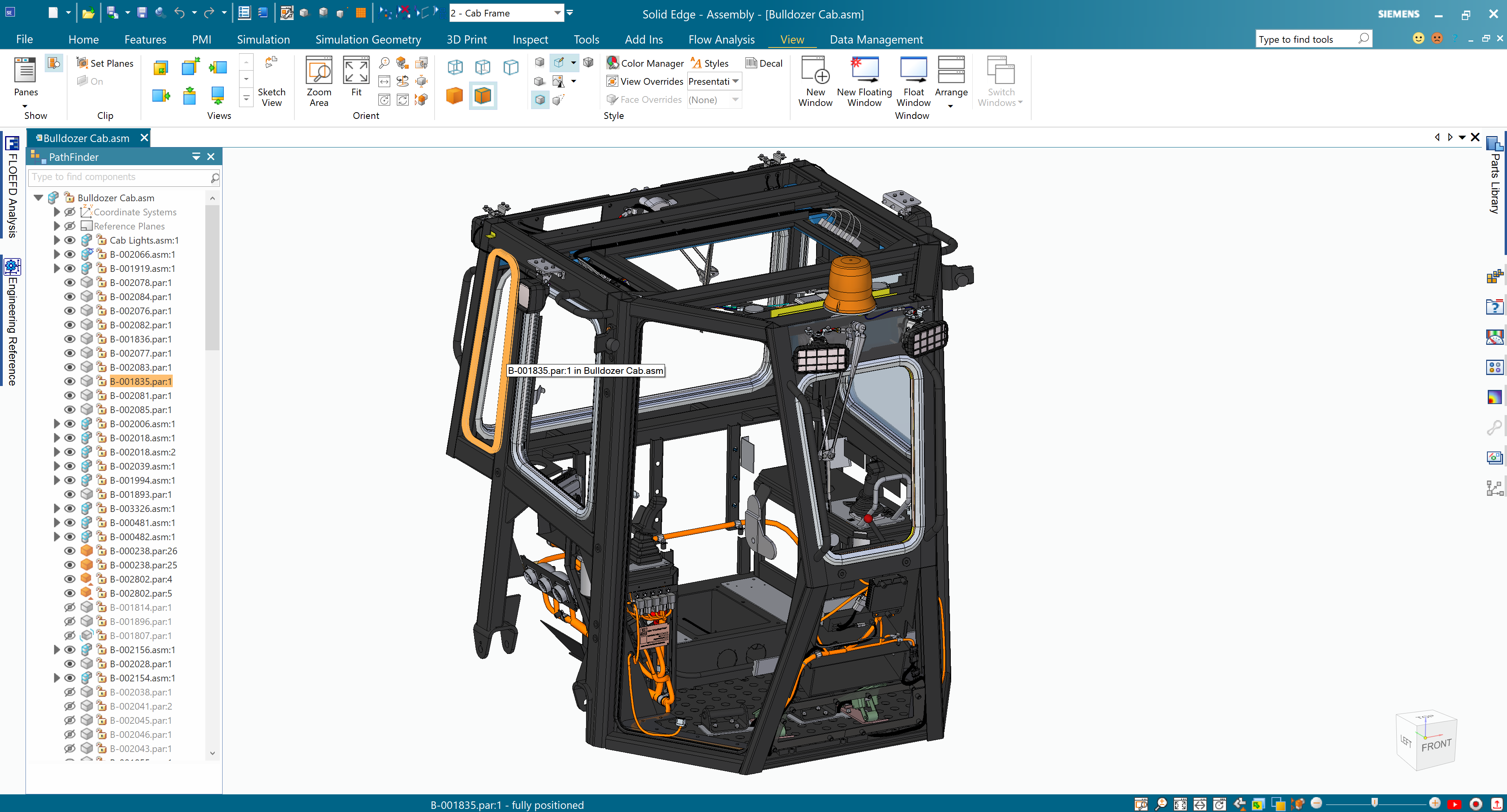
With assembly modeling tools in Solid Edge, you can easily update relationships and constraints, whether you are modifying existing parts, or importing new assemblies. Textual and symbolic representations of assembly components and their relationships, organized in an outline format, make it simple to find, activate, and control their display.
Save time with patterning and standard parts
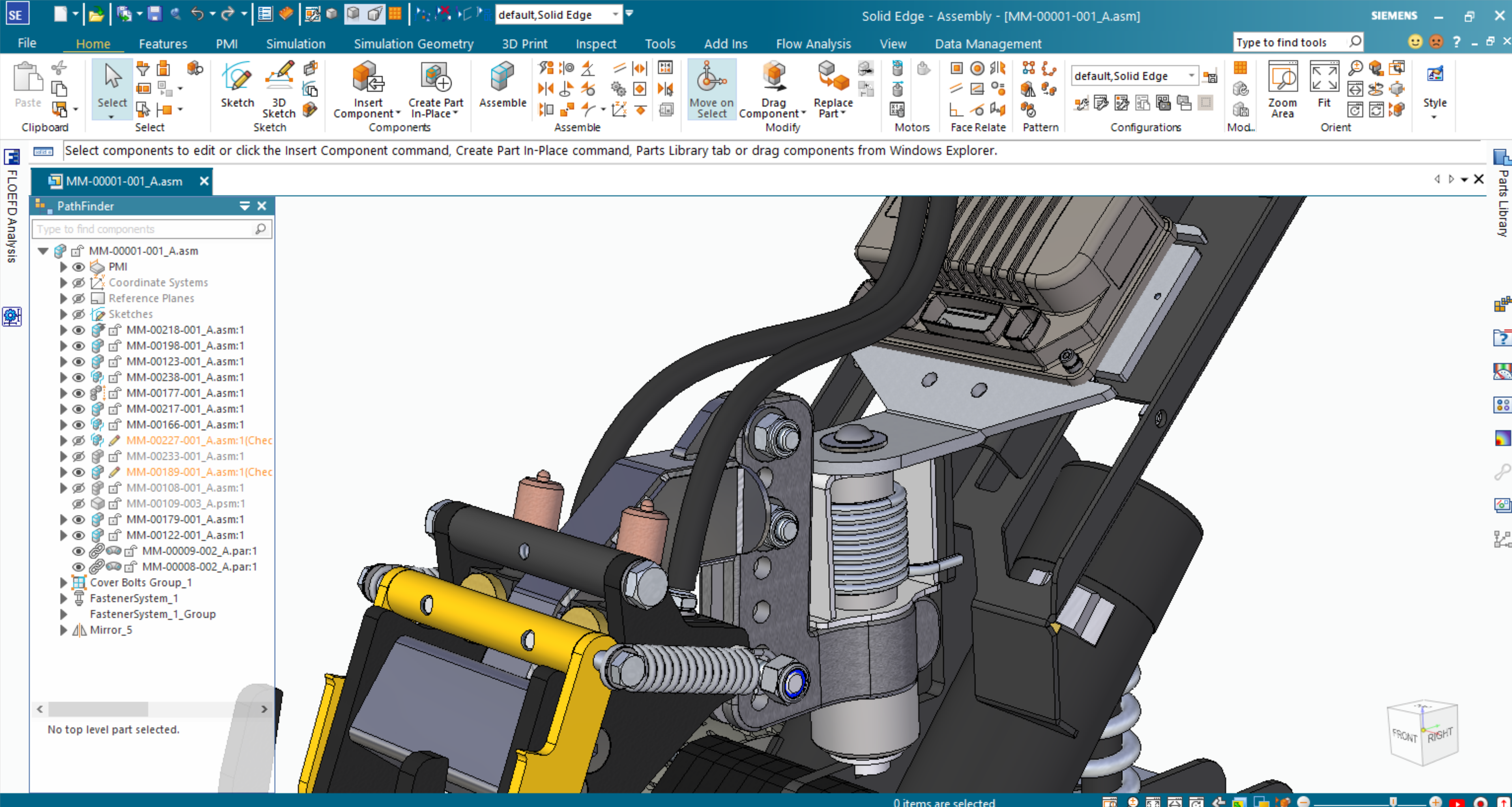
When building assemblies, you often need to place standard or commercially supplied parts, like nuts or bolts, and subassemblies multiple times in a pattern or mirror arrangement. With Solid Edge, you can quickly copy parts and subassemblies into a pattern arrangement. Users may copy and paste internal, external, and learned relationships so newly placed parts get assembled with a minimum number of clicks. Internal occurrences of parts from subassemblies and the subassemblies themselves can be copy and pasted, along with parts, allowing you to reuse internal components, including constraints. Solid Edge also supports a lightweight mode for locating inactive components. And, with available part libraries, you can easily find and place commonly used parts that comply with your company standards.
Faster design of frames and weldments
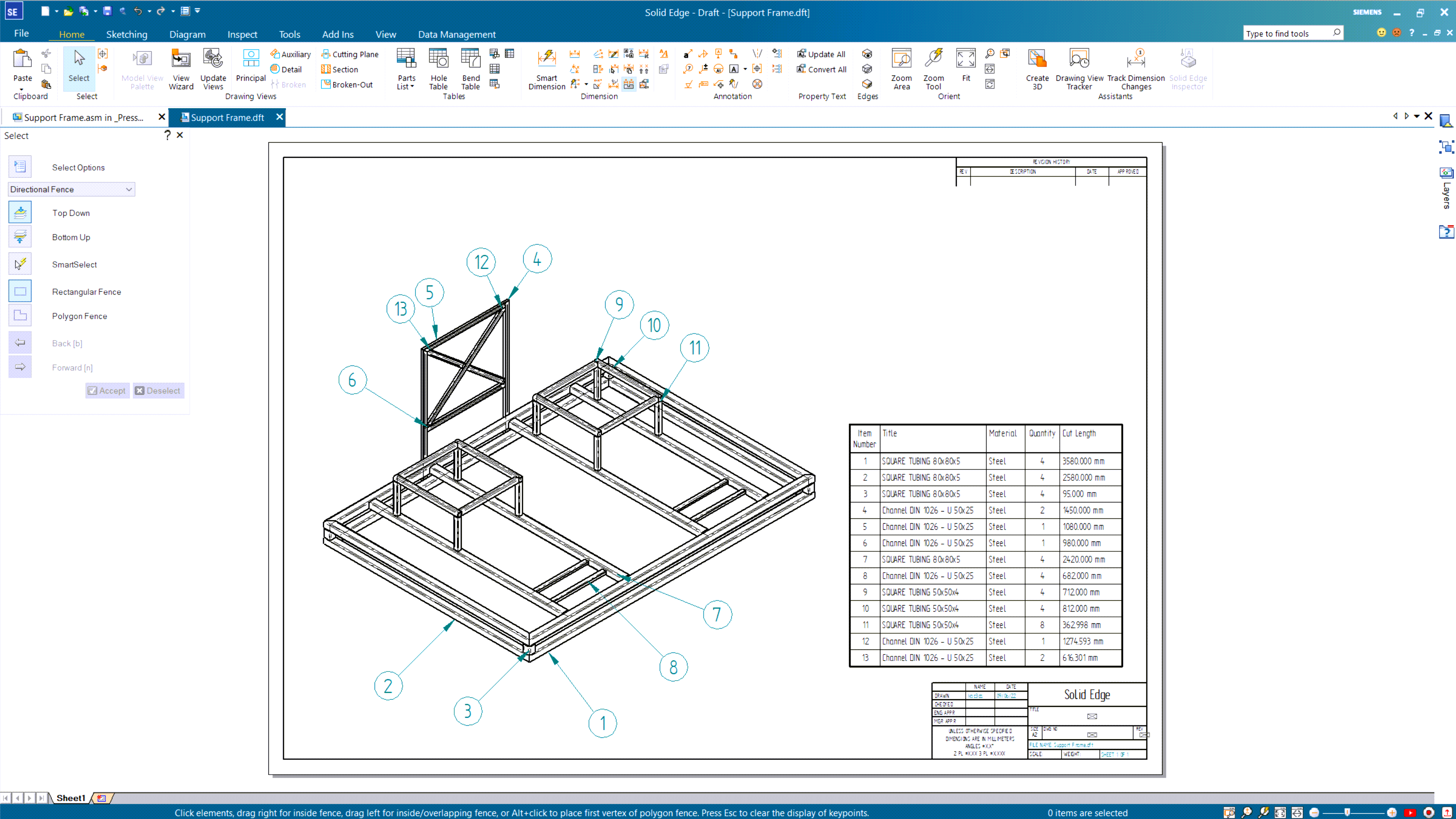
Solid Edge includes process-specific applications to speed the creation of rigid frame structures and weldments. Embedded engineering process knowledge, along with structured workflows, help you design frames and weldments much faster than with general-purpose CAD modeling tools. Solid Edge frames and weldments are fully associative with Solid Edge assembly, part modeling and drafting capabilities. And Solid Edge allows you to automatically create a parts list that includes cut lengths for each component, customizable for downstream viewers in manufacturing or purchasing.
Speed translation of imported files
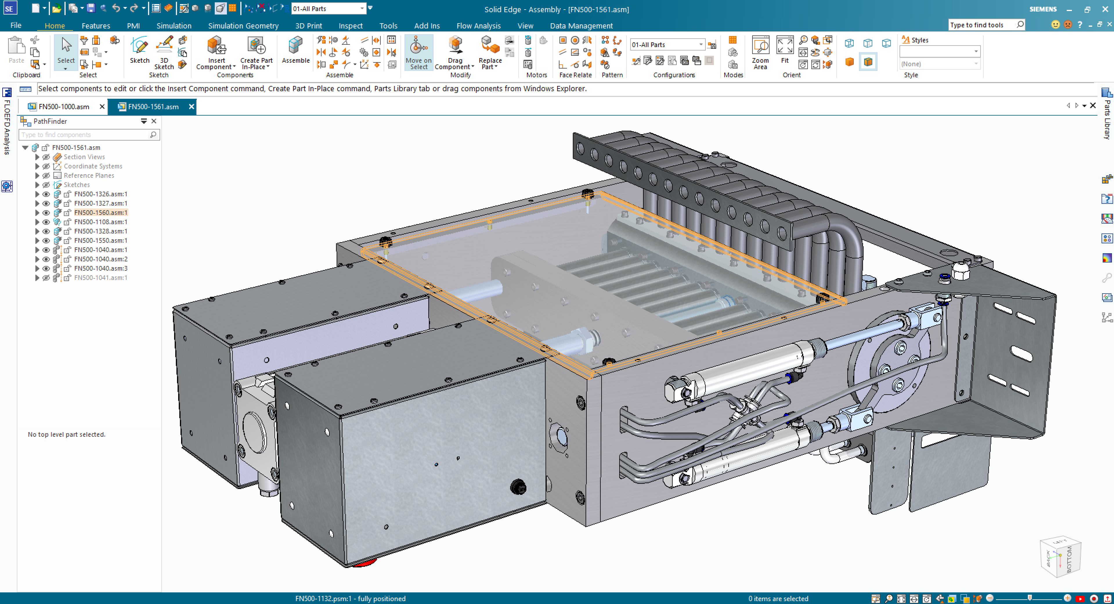
Negate the need to access external data after importing files. The internal components workflow included in Solid Edge automatically embeds component information from imported files into the Pathfinder, putting the data directly in an assembly in a matter of seconds. Internal component structures are converted to traditional file structures. When dragging components, assembly manipulation retains both internal and external references. Templates for part, sheet metal, and assembly files aid in publication. Solid Edge supports the import of x_t (Parasolid), STEP, JT and IFC data formats.
Realistic assembly rendering and animation
Solid Edge helps bring designs to life with full photo-realistic rendering, including graphical light placement, soft shadows, and reflections. Realistic motion simulations can be created with powerful explode tools, saved as movies, and shared. A sophisticated time-line helps designers set the exact sequence of operations showing when motors start, shafts rotate, parts fade and explosions occur.
Video
Large assembly management in Designcenter Solid Edge
One of the biggest issues when working on large assemblies is how much time it takes to open and load all of the parts. Designcenter Solid Edge accommodates for this by giving you full control of exactly how a large assembly is opened.
Solid Edge Large Assembly Modeling
In this video, you will see how Solid Edge handles large assemblies. Solid Edge provides you with all the tools you need to work more efficiently in assemblies, whether your CAD model has 10 parts, 13,000 parts, or even 2.5 million parts.
