3D CAD Tutorial: Robot Claw
3D CAD Tutorial: Robot Claw
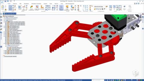
This tutorial instructs users to create a 3D assembly with moving gears, components, and restrictions to create an articulated mechanical claw.
Level:
High School, College
Difficulty:
Advanced
Select the following link to install the free Siemens Solid Edge 3D CAD software for your classroom (www.siemens.com/plm/solid-edge-highschool). Students can download and install their own free copy of Siemens Solid Edge. (www.siemens.com/plm/solid-edge-student).
Download the annotated text guide with pictures or follow along with the video below.
- Start by creating a NEW part file using a Metric Part template.
- Select the Line command and lock to the (x,y plane) by pressing F3 when the plane highlights under the cursor.
- Press CTRL+H to orient to the sketch view.
- Click on the origin as the start point and then press “S” to create a Symmetric line about the origin point.
- Sketch a Horizontal Line that is 50 mm long.
- Select the Symmetric Offset command found on the drop-down menu under the Offset command.
- Set the width to 9 mm and toggle on Offset Arc in the Symmetric Offset options
- Select the horizontal line to offset “from” and click the green checkmark or right click to accept.
- Press CTRL+I to orient to an isometric view
- Select the region created by the sketch and click an arrow to begin extruding into a 3D feature.
- Tap “Shift” to extrude symmetrically and key-in 9.5 mm for the height.
- From the PathFinder, expand the Base Reference Planes entry and toggle on the Top Ref. Plane.
- Select the Circle by Center Point command and lock to the Top plane.
- Press CTRL+H to orient to the sketch view.
- Sketch a circle that is concentric with the arc and the same diameter as the arc.
- Press CTRL+I to orient to an isometric view
- Select the Extrude command from the Command Ribbon.
- Change the selection option to “Single” in the QuickBar.
- Be sure the option is set to ADD material
- Select the circle and extrude symmetrically 12.5 mm
- Select the Circle by Center Point command and lock to the Top plane once again.
- Press CTRL+H to orient to the sketch view.
- Sketch five 4.25 mm circles as shown.
- One at each end; one in the center; tw * offset from the center
- Press CTRL+I to orient to an isometric view
- Select the Extrude command from the Command Ribbon.
- Set the selection option to “Single” in the QuickBar.
- Be sure the option is set to SUBTRACT material
- Select the circles and extrude symmetrically through the part.
- Hide the PMI dimensions, Ref. Plane and Sketches by unchecking those entries in PathFinder.
- Select the Project to Sketch command from the Home tab.
- Lock to the top face of the part for the Sketch Plane
- Select the option to Project with Offset and click OK
- Set the distance to offset as 1.5 mm
- Select each of the 4 circles on that face and offset each one to the outside.
- Change the Select option in the Quickbar to “Single Face” and offset the face edges to the inside.
- Select the 4 regions resulting from the intersecting sketches.
- After selecting the first region, press the spacebar to multi-select the other 3 regions.
- Select the arrow and drag into the part 4 mm to create blind pockets.
- Tap the “Shift” to toggle off symmetric cut
- Hide the sketches and PMI dimensions from PathFinder.
- Show the Top Ref. Plane once again
- From the PathFinder, select the last Cutout feature.
- Select the Mirror command.
- Select the Top Ref. plane as the Mirror Plane
- Press Esc to exit the select set
- Hide the Top Ref. Plane
- Double click the Material entry in PathFinder to open
the Material Table.- Expand Non-Metals > Plastics
- Select ABS Plastic, high impact
- Click Apply to Model
- Close and Save the model as CLAW LINKAGE.par in the ../ROBOT CLAW/Library folder.
Download the annotated text guide with pictures or follow along with the video below.
- Start by opening the Claw Assembly.asm from the ROBOT CLAW folder.
- Expand the Parts Library from the fly-out menus.
- Navigate to ..\ROBOT CLAW\Library folder
- Select the CLAW LINKAGE part you just completed modeling.
- Place your cursor in the Preview window at the bottom of the Parts Library and rotate the preview by pressing and holding the middle mouse button (wheel) and dragging.
- Orient the part close to the orientation it will be in the assembly.
- This orientation will be remembered when you drag the part into the assembly and will be easier to assemble.
- The default assembly relationship is FlashFit.
- If the first face selected is a planar face, the relationship created will be a mate or planar alignment.
- If the first face selected is a cylinder, the relationship created will be an axial alignment.
- Select the bottom face of the stepped area of the CLAW LINKAGE part and mate to the top face of the bottom plate of the Gripper Assembly.
- Select the hole in the stepped end of the CLAW LINKAGE and align to the Pin in the end of the Gripper Assembly
- In the Parts Library, select the CLAW LINKAGE part again.
- Place your cursor in the Preview window at the bottom of the Parts Library and rotate the preview to orient the part for the other side.
- Repeat the same steps described above to assemble it into position.
- Next, find the FLAT CLAMP JAW in the Parts Library and orient the preview for assembly as the previous parts.
- Drag in the JAW part.
- Mate the face of the JAW slot to the bottom of the LINKAGE part.
- Next align the two holes in the JAW to the 2 end holes of the LINKAGE parts.
- Repeat the previous steps to add a jaw to the other side.
- From the Parts Library, drag the CLAMP-PIN-LONG.par into the graphics area.
- Press ESC before adding any relationships.
- Drag in CLAW-SNAP.par and assemble to the groove in the bottom of the pin.
- Aligning a circular edge to a circular edge with FlashFit will automatically create a planar alignment and a cylindrical alignment in one step.
- Now let’s create a NEW subassembly of the CLAW-PIN-LONG and CLAW-SNAP.
- Select both parts graphically, or from the PathFinder, and select the Transfer command.
- Highlight the top assembly and select the New Assembly button.
- Point to the Library folder as the save location and name the new assembly: LONG PIN ASSEMBLY.
- Click OK to dismiss the Transfer dialog.
- Now that we have a subassembly we need to assemble it in place.
- First we need to remove the Ground relationship that is added when the subassembly was created with Transfer.
- Select the LONG PIN ASSEMBLY in PathFinder and in the bottom pane of the PathFinder select the Ground relationship and press the delete key.
- With the Pin assembly still selected, click the Assemble command.
- Pick the bottom edge of the head of the pin. This may require using QuickPick to get the correct edge.
- Select the top edge of a hole in the FLAT CLAMP JAW.
- This adds a mate and an axial alignment.
- We need to place 3 more Pin assemblies, so let’s capture the relationships in the Pin subassembly to use for the other locations.
- Select the LONG PIN ASSEMBLY in PathFinder.
- Select Capture Fit command from the Assemble collector.
- Click OK to learn the relationships.
- From the Pathfinder, Select the LONG PIN ASSEMBLY and drag another copy into the graphics window.
- Note the bottom face of the pin highlights for the Mate relationship.
- Select the top face of the FLAT CLAMP JAW as the target for the mate.
- Next a cylinder in the Pin highlights for the axial alignment.
- Select the other hole in the FLAT CLAMP JAW as the target for the alignment.
- Drag in 2 more Pin Assemblies from the PathFinder and select the target faces and holes on the other FLAT CLAMP JAW part for each.
- Notice that in the PathFinder, near the top, that the two CLAW GEAR LINKAGE parts are grounded.
- You can tell this because of the blue box in the corner of the icons.
- Select each one and delete the Ground relationship in the bottom pane of the PathFinder.
- Select the Drag command and graphically select the jaw closest to you.
- Hold down the left mouse and begin to drag to see the motion of the jaw.
- Note only one jaw is moving
- Click Reset in the Quickbar and escape the command.
- We need to add a Gear relationship between the two CLAW GEAR LINKAGE parts.
- Click the Assemble command and change the relationship type to Gear from the drop down.
- Select a cylindrical face of one of the CLAW GEAR LINKAGE parts to select its centerline.
- Select the corresponding face on the other CLAW GEAR LINKAGE parts to pick up its centerline.
- Be sure the Green arrows are showing the rotation in opposite directions.
- If they show the same direction, click the Flip button at the end of the QuickBar.
- The gears are the same size and number of teeth, so the ratio can be left at 1:1.
- Click OK to complete the creation of the Gear relationship.
- Select the Drag command again and graphically select either jaw.
- Hold down the left mouse and begin to drag to see the motion of the meshing gears and the realistic movement of the jaws.
- NOTE – the limit of the jaw’s motion is due to a predefined Path relationship to a sketch defining the limits of the jaw.
- Save your assembly.
Congratulations! This concludes the exercise.
Don’t stop here!
Improve 3D Spatial Thinking and Creativity with more examples on the GearupU website. Developed by a Utah State design and engineering teacher focusing on STEM to STEAM, GearupU exposes students to a world of amazing patterns, shapes and artistic designs and gets them excited about STEM. Students with no background in 2D or 3D design should start with Class 1.
Solid Edge for Students
With Solid Edge, students have access to a free version of the same easy-to-use software suite used by professionals. In addition to free software, we provide tutorials, webinars, online courses and certification to help you develop your design and engineering skills.
Training that fits your needs
Get free access to topic-based or project-based tutorials, online self-paced courses and interactive learning resources. Training materials can be used to learn Solid Edge on your own, or to supplement classroom learning. Students can also achieve Solid Edge Certification for a competitive edge when applying to jobs.
A vibrant online and offline community
Access our online Solid Edge User Community, including a dedicated forum for students. Learning Solid Edge also gives you the opportunity to participate in a variety of projects and competitions, including the Greenpower Challenge and Siemens Digital Industries Software Student Design Contest.
We also offer a University Edition that includes more capability for a site-wide implementation. Instructors should visit Solid Edge Resources for Educators for details.
Learners of all ages can gain valuable experience with industry-leading technology, supporting your studies in STEM subjects at all levels of education, from elementary school through university.
How would you rate this content?[thumbs-rating-buttons]