A better approach for meeting very short lead times
A better approach for meeting very short lead times
CHALLENGES
- Very short lead times
- Many product variants
KEYS TO SUCCESS
- Transition from SolidWorks to Solid Edge
- Strong assembly modeling, sheet metal and weldments design functionality
- Fast drawing creation
- Parasolid kernel compatibility with other CAD and CAE programs
- Insight for design management
RESULTS
- Better ability to meet short lead times
- Virtual prototyping replaces physical testing
- More design re-use; part count down by 50 percent
- Easy data exchange with major customer and outside analyst
Freedman Seating Company
Freedman manufactures seats and seating-related products for small and midsize buses, heavy-duty transit, paratransit, vans, commercial vehicles, rail cars, trucks, specialty vehicles, and more.
www.freedmanseating.com
New Products Engineering Manager,
Freedman Seating Company.
Moving from SolidWorks to Solid Edge improves the design process while ensuring data compatibility with customers and suppliers
New Products Engineering Manager, Freedman Seating Company.
Not just seats
Freedman Seating Company (FSC) began 120 years ago when founder Hyman Freedman began making seat cushions for horse-drawn buggies. He knew his craft and was awarded an honorable mention at an 1892 exposition in Chicago for his skill in upholstery. A century later, FSC is still a family-owned and operated business, although it is now one of the nation’s largest specialty seating manufacturers, with more than 500 employees.
FSC manufactures seats and seating-related products for many different applications. Its products fall into three categories: 1) bus seating, 2) rail seating and 3) truck, specialty, and commercial vehicle seating. Customers include the major original equipment manufacturers (OEMs), more than 250 bus distributors, the federal government, and many states and municipalities.
FSC’s product development process is characterized by very short lead times. “It’s a cash-flow issue,” explains Pasquale Di Rico, new products engineering manager at FSC. “These vehicles are expensive; a bus can cost half a million dollars. When a manufacturer gets an order, they want to get it built and inspected and delivered to the customer as soon as possible, and a vehicle can’t be inspected until the seats are installed.”
Another challenge facing FSC’s new product development team is the large number of product variants the company offers. “Think of how many cities, towns, and universities there are,” Di Rico says. “There are a lot of regulations driving our designs, and we have more variations of seats than the whole automotive world combined.”
Needed: virtual prototyping and PDM
Over time, FSC’s 2D design process, which utilized AutoCAD® software, grew less effective at helping the company meet these challenges. What FSC needed was a 3D design process that would enable virtual prototyping. “We don’t have time to make physical prototypes,” Di Rico notes. “We needed to be able to design in 3D and go into production immediately.”
Another necessity was a product data management (PDM) system, which would make it easier to keep track of all the seat variants. Also, a PDM system’s search capability would foster the re-use of existing designs, a practice that would help in meeting the short lead times. Finally, FSC’s seats have contours and sweeping surfaces, particularly the foam interior components. “We couldn’t even model those in the 2D environment,” Di Rico adds.
The company initially chose SolidWorks® software as its 3D design solution, mainly because more people were using it, according to Di Rico. Users were trained and had started using the new software to a limited extent when a joint venture partner suggested a better option: Solid Edge® software from Siemens Digital Industries Software.
“That company had a product line that we were going to take over, and all the designs were done in Solid Edge,” says Di Rico. “We saw some nice advantages in Solid Edge for sheet metal and weldments design, as well as a more robust assembly design environment.”
Solid Edge comes with the Insight™ design data management solution, which was also an attractive feature for FSC. Another reason it made sense to switch to Solid Edge was that one of FSC’s main customers, with whom the company exchanges a lot of geometry, uses NX™ software from Siemens Digital Industries Software. NX and Solid Edge are both built on the Parasolid® software geometric modeling kernel, eliminating the need for data translation between the two systems.
The right choice
“We made the decision to move to one platform and that was Solid Edge,” Di Rico continues. FSC purchased 24 Solid Edge licenses, which are shared among 30 users. Di Rico put together a transition plan that included some training from its Siemens Digital Industries Software partner, Geometric Solutions, as well as the use of built-in Solid Edge tutorials.
“The tutorials are very good in Solid Edge, and better than those that had come with SolidWorks. These days, new users don’t go to training. They learn from the tutorials and their colleagues that Solid Edge is pretty self-explanatory depending on your level,” says Di Rico. And FSC gets ongoing technical support from Geometric Solutions. Di Rico acknowledges that “there was some grumbling” when users learned they were changing CAD systems, but says, “Moving from SolidWorks to Solid Edge was a very natural process.”
FSC has since used Solid Edge to design many new seats. “We find its solid modeling functionality very friendly and best-in-class for us,” explains Di Rico. “Also, we make a lot of assemblies, and there are many tools in Solid Edge for doing that quickly.”
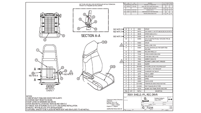
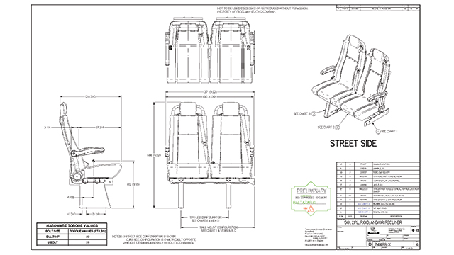
He appreciates the software’s drawing functionality, which lets the design team easily generate drawings from their Solid Edge assembly models. “We have dozens of customers using 3D CAD and we exchange 3D data with many of them, but we still send out 2D drawings to the others who want them,” he adds.
Faster cycle times
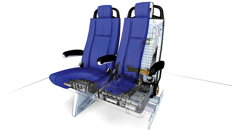
The transition to Solid Edge is helping FSC meet its short lead times in a variety of ways. First, the software supports the company’s desire to work exclusively with virtual prototypes. Solid Edge assembly modeling and visualization capabilities allow the design team to create virtual mockups of the seats inside a vehicle to look at issues such as spacing and accessibility. Finite element analysis (FEA) lets them simulate structural performance without testing and building physical prototypes. The analyst works directly with the Solid Edge design geometry.
Another way the use of Solid Edge helps with the short lead times is by fostering design re-use. “Insight has search tools that are quick and at-hand, and people are more likely to find a part to re-use,” Di Rico adds. “We’re trying to move to using more standard parts. We have reduced our part count by 50 percent and we’re working to reduce it further.” When FSC is ready to deploy additional product lifecycle management (PLM) functionality, the extensibility of the Insight database into Siemens Digital Industries Software’s Teamcenter Express solution will simplify that process.
Di Rico appreciates the ongoing development of Solid Edge. “Siemens Digital Industries Software is putting a lot into improving Solid Edge, to the point where they have even come here to find out how they can make the software better meet our needs,” he says.