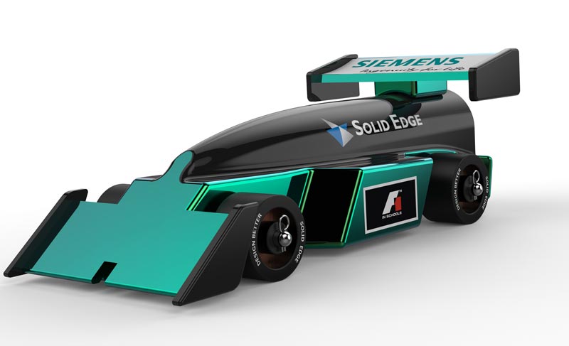
Build a racecar with assemblies and motors
Build a racecar with assemblies and motors
Follow this in-depth Solid Edge tutorial to build a racecar with sketching, protrusions, assemblies, motors, gears, and gear relationships.

Level:
Sekundarschule
Difficulty:
Fortgeschrittene
Select the following link to install the free Siemens Solid Edge 3D CAD software for your classroom (www.siemens.com/plm/solid-edge-highschool). Students can download and install their own free copy of Siemens Solid Edge. (www.siemens.com/plm/solid-edge-student).
Download the annotated text guide with pictures or follow along with the video below.
- Start your design using the F1 Model Block and the Virtual Cargo body template. (F1inSchools_Blank-Cargo.par)
- Uncheck the feature in PathFinder to hide the Virtual Cargo body.
- Add a new body to create actual Car Body design.
- Add Part body and name it “Car Body”.
- Click on the Project to Sketch command.
- Using the orientation cube in the lower right corner, click on the Right view.
- Press F3 to lock to the Right plane.
- Select the bottom edge of the F1 blank to project to the plane.
- Draw a 10 mm diameter circle tangent to the left edge of the F1 blank and 12 mm from the bottom edge.
- Add angled lines tangent to the circle on the top and bottom as shown.
- Add a vertical alignment between their endpoints.
- Sketch 2 more lines approximately as shown.
- Add dimensions using the Smart dimensioning tools to get the desired shape and size.
- Press CTL+I to orient to an isometric view.
- Select the closed regions formed by the sketches and begin to drag into 3D.
- Press the Shift key to toggle on symmetry to drag in both directions.
- Drag the 3D body 64 mm.
- Select the circle command and use F3 to lock to the end face of the stock body with the hole.
- Sketch a 32 mm diameter circle concentric with the hole in the stock body (This is also the origin of the base coordinate system).
- Sketch 2 lines tangent to circle and extending vertically to silhouette edge of the end cylindrical face of the first extrusion.
- Touch the edge arc of the extrusion to align to the silhouette point.
- Close the sketch.
- Uncheck the F1 blank feature to hide the stock body
- Select both regions formed by the sketches extrude into the body 70 mm.
- Use the Shift key to toggle symmetry off and the Space Bar to toggle Adding material.
- Turn on the display of the F1 Blank feature.
- Using the Project to Sketch command again, lock to the end face of the F1 Blank.
- Select the circular edge of the bore in the F1 blank.
- Select 3 edge of the slot.
- Use the region of the circle to cut a hole in the Car Body that is 52 mm deep.
- Hide the stock body and rotate the model so you are looking at the bottom of the part.
- Select the extrude command and change the selection option to chain in the command bar.
- Select one line from the slot profile to chain will select all 3 lines.
- Right click to accept the selection and then move your cursor to point the arrow to the inside of the U-shape as the side of the open profile to remove and click to set this option.
- Press the spacebar to toggle removing material and drag the profile completely through the part and finish the cutout.
- Next we want to create a lofted extrude to add aerodynamic features to the car.
- Select the Point command and lock to the top face of the car body using F3.
- Touch the right edge of the locked face to find its midpoint to align with and click to create a point on the face.
- Add a Smart dimension to the Point and make it 10 mm from the edge.
- Select the Loft command.
- Select Face option in dropdown menu to select front face of cartridge housing.
HINT: be sure the point appears at the end of the tangent line as indicated by the red arrow.
- Change the selection option to Point from dropdown and select the sketch point.
- Click the Preview in the command bar or right mouse click to preview the Loft.
- From the tangency control drop down, select Tangent Continuous.
- Set to 1.500
- Click Finish.
- Rotate the model to see the bottom face (slot side).
- Select the Rectangle by Center command and lock to the bottom face of the car body using F3.
- Select “Bottom” on the view orientation cube in the lower right.
- Sketch a rectangle centered on the edge of the body.
- Add dimensions to size and locate the rectangle.
- Mirror the rectangle about the Y axis.
- Use the regions created by the rectangles to cut wheel well slots in the car body.
- Select the wheel well cutout features from the PathFinder (last Cutout feature).
- In the command bar select the option to move with copy.
- Select the arrow on the steering wheel to initiate a synchronous copy/move.
- Copy the cutout 100 mm to the front of the car body.
- Select the front face of the last cutout and select the arrow to start a synchronous edit.
- NOTE: symmetry automatically selects the face on the opposite side.
- Drag through the end of the part.
- Add 100 mm radius rounds on the top and bottom edges between the top face of the body and the rear angled faces.
- Add to both sides of the car
- Select the Circle command and lock to the inside face of the rear wheel well.
- Select the Right orientation using the view cube.
- Sketch two 5 mm diameter circles approximately as shown; be sure that they are in horizontally aligned.
- Add concentric 26 mm circles to represent the size of the wheels and set these 2 circles to construction.
- Add dimensions shown to fine tune their locations.
- Add holes for wheels using extrude cut
- Using the regions created by the inner circles, drag holes completely through the part.
- Right click in the graphics window to bring up the shortcut menu and select the option to Transitioned to Ordered at the bottom of the menu.
- Add rounds to the following area:
- Add 3 mm rounds along cylindrical cockpit.
- Add 2 mm rounds to the front 4 corners of the fuel tank area and then to the top and bottom edges.
- Add 1 mm rounds to the rear wheel wells and back of the cockpit housing.
- Click on the check box next to Virtual Cargo in the Pathfinder to bring the part into view.
- Select the virtual cargo by clicking on the part or selecting from the pathfinder.
- Click on the bottom arrow to drag the part downward.
- Drag the part into the car body such that it is completely inside.
- Check by switching the view to wired view under the view tab.
- Return to the normal view and uncheck the virtual cargo from the Pathfinder.
- From the view tab, use Part Painter feature to paint the cockpit are to your the desired color’.
- Save part with a new name to avoid overwriting original template.
Download the annotated text guide with pictures or follow along with the video below.
- Start your front wing design by using the previously made F1 Body design part. (Car_Body.par)
- Create a new assembly.
- Select “Assembly of Active Model” option
- Save the new F1 assembly ex. (My_F1_Car_Assembly.asm)
- Create new part in place.
- Select “Create Part in Place”.
- Select OK when dialogue box comes up.
- Select Polyurethane for material in dropdown menu.
- Click Green checkmark button.
- Save the part file ex. (front_wing.par)
- Click on the Project to Sketch command.
- Using the orientation cube in the lower right corner, click on the Right view.
- Press F3 to lock to the Right plane.
- Select both front edge and bottom edge of model.
- Click on the offset button to create offset line parallel to front edge.
- Change the distance to 3 mm.
- Create a line perpendicular to
both front edge and offset line. - Select the trim button to trim
the remaining line on the sketch. - Create angle dimension for the sketch.
- Set 40° angle between offset line and bottom edge.
- Lock the angle using the locking button.
- Set vertical distance for the wing using smart dimension.
- Select horizontal side and angled side to create the dimensions.
- Set measurement to 20 mm.
- Click on the region inside the sketch and extrude using the arrow which pops up.
- Press shift to toggle symmetry.
- Set extrude to 80 mm.
- Click on the line command.
- Hover the cursor over the end face of the previous extrusion until it highlights.
- Press F3 to lock the plane.
- Press CTRL+H to orient the view to
the plane
- Sketch 3 lines similar to the ones
shown in picture. - Create fourth line by offsetting the edge with the wing.
- Use the Project to Sketch button.
- Select “Project with offset” option and click OK.
- Select the edge with the wing and offset by 3 mm.
- Use the Trim Corner command to connect the ends of the sketch lines.
- Click and drag around the corners to remove extra lines or to extend the corners.
- Using Smart Dimension, add dimension
to the sketch as shown. - Select both sketch and outer face of wing to extrude.
- Select the add options in extrude toolbar.
- Deselect the symmetric option.
- Extrude 3 mm into the wing.
- Add rounds to wing’s outer body.
- Select the edge/corner option from the dropdown menu.
- Select the two acute edges and set their radius to 1 mm.
- Select the two obtuse edges and set their radius to 5 mm.
- Use the Face option from dropdown menu to round entire end face.
- Set radius to 1 mm.
- Use mirror option to copy the outer body on one side of the wing to the other side.
- Select the entire outer feature by clicking and dragging
a box around the geometry. - Select the Mirror button.
- Select the right plane using the coordinate system.
- Select the entire outer feature by clicking and dragging
- Use the Part Painter on the View tab to color
the wing support structure Black (dull).- Click and drag around the structure.
- Create a projection of the slot in the bottom of the car body.
- Select project to sketch button.
- Lock to the XZ plane from the coordinate system.
- Select the 3 edges of the slot in the front of the car body.
- Add slot in the wing by removing material.
- Click on the Extrude command.
- Select chain option from dropdown menu.
- Select the 3 projected edges on the XZ plane with one click.
- Select the cut option from dropdown menu.
- Point the arrow to the inside of the slot shape and click.
- Drag the cut through the front wing.
- Isolate the wing by hiding the rest of the body by pressing CTL+Q.
- Add a “Rectangle by center” to the top thickness face of wing.
- Define the center of the rectangle to be on the
midpoint of the edge of the face. - Add dimensions to the drawing as shown.
- Define the center of the rectangle to be on the
- Click on the region defined by the sketch and select arrow to extrude 10 mm towards the slot.
- Show the Car Body (CTRL+Q) and notice how the wing interferes with the body.
- Click on the Subtract command on the Features tab.
- Select the Body as the target for the subtraction.
- Select the Front Wing as the tool body.
- Click on the Subtract command on the Features tab.
- In place activate into the car body by clicking the Edit in place button
after selecting the body, and notice the new pockets in the car body
for the Front Wing. - Select the bottom face of the Front wing key slot.
- Remove the material by dragging the face downward through the bottom slot.
- Add Rounds to the edge of the extrusion.
- Use the edge/corner option from dropdown menu.
- Add 0.5 mm rounds to the edges.
- Add round to the front of the car body.
- Use the chain option from dropdown menu.
- Type in radius of 1 mm.
- Select the edge of the front face of the car body.
- Close and return to the assembly.
- Isolate the Front Wing by selecting it and clicking on the Edit in place icon.
- Click the Round command and select the top edges of the feature.
- Add 1 mm rounds.
- Click arrow underneath round button for more options.
- Select Chamfer Equal Setbacks option.
- Select the edge of the extrusion.
- Set the setback distance to 0.5mm.
- Finally round the bottom front edge of the wing using the round button.
- Set round to 1mm.
- Select Close and Return to go back to the top level assembly.
- Save the assembly.
- You have now completed the Front Wing of the F1 Car.
Download the annotated text guide with pictures or follow along with the video below.
- Start your rear wing design by using the previously made F1 Body design assembly. (My_F1_Car_Assembly.asm)
- Create new part in place.
- Select “Create Part in Place”
- Select OK when dialogue box comes up.
- Select Polyurethane for material in dropdown menu.
- Click on the Green checkmark button.
- Save the part file ex. (rear_wing.par)
- Orient the model in order to sketch on the correct plane.
- Using the orientation cube in the lower right corner, click on the Right view.
- Press F3 to lock to the Right plane.
- Click on the arc button and select “Arc by 3 Points”.
- Draw an arc using 3 points above the car body.
- This is an estimation and correct dimension will be applied later.
- Using the line sketch feature, draw a line starting from the centerline of the rear wheel axle upwards.
- Click on the connect button in Relate section to align the arc center to the vertical line.
- Using the same connect button, connect the arc and the centerline to remove the remaining arc segments.
- Draw another line from the arc centerline to the other end of the arc.
- Click on the construction button and select both straight lines.
- Using the smart dimensions, define the radius of the arc 70mm.
- Define the angle of the arc 25 degrees.
- To define the thickness of rear wing:
- Offset the arc by clicking on the offset button and selecting the arc.
- Offset the arc to the inside 3 mm.
- Sketch an angled line from the lower endpoint of the arc
- Line should be at a 135° angle as shown.
- Press the tab key to enter the angle dimensions instead of length.
- Sketch a circle on the trailing edge to create the back end of the wing.
- Select the tangent circle option from the dropdown menu.
- Place the circle between the two arcs.
- Apply a third tangent relationship between the arc and the angled line as shown.
- Taking advantage of the synchronous technology, click and drag a box around the sketch to select the enclosed shape.
- Extrude the enclosed shape 80 mm.
- Press shift to toggle symmetry.
- Since we no longer need the sketch, we can delete the sketch in the pathfinder.
- Sketch 3 lines on the center plane to create the mounting structure for the rear wing.
- Using the smart dimensions, add a few dimensions to the sketch.
- Use the extrude feature to create a solid extrusion.
- Extrude the structure 20 mm symmetrically.
- Make sure to select chain option from the dropdown menu.
- Use the subtract feature to subtract the wing from the car body.
- Add rounds to the model to make it aesthetically pleasing.
- Round the 4 corners on the support structure.
- Sketch a rectangle by center on the back side of the wing.
- Dimension the rectangle 3 mm wide and 6 mm height.
- Extrude the lower region of the rectangle.
- Extrude 22 mm towards the leading edge of the wing.
- Using the Pathfinder, delete the rectangle sketch.
- Use the coincident plane feature to create a plane coincident to the side of the mounting structure.
- Using the steering wheel, translate the plane so that it is coincident to the end face of the wing.
- Use the new sketch plane to create a sketch for the support structure at the end of the wing.
- Use smart dimensions to add a few measurements to the sketch.
- Select the sketch and the wing arc to extrude 3mm towards the center plane.
- Add rounds to the 4 corners of the structure for aesthetic purposes.
- Select face round option in the drop down menu to add round to the entire face of the support structure.
- Click and drag a box around the entire support structure to select it.
- Mirror the entire structure across the center plane using the mirror feature command.
- Use part painter feature to paint the two end structures of the wing.
- Paint the structures Black (dull).
- Click on the “Close and Return” button to close and return to the top level assembly.
- Use the subtract feature to subtract the rear wing body from the car body to remove the interference
- Uncheck the box next to rear wing part in the pathfinder so that you can see the slot in the car body.
- Click on the car body and select edit in place
- Extend the resulting slot by dragging the end face beyond the edge of the part
- Also drag the front end of the slot an extra 2 mm.
- Add rounds to the corners of the slot using the Round feature.
- Specify a 0.5 mm radius for these
- Click on “Close and return” button to exit and return to the assembly.
- Check the box next to rear wing part in pathfinder to see the entire assembly.
- Select the rear wing and click Edit in Place option to work with only the wing.
- Add chamfers to the bottom edge of the key.
- Select “Chamfer Equal Setbacks” from the dropdown menu.
- Add 2 mm rounds to the bottom of the wing.
- Make sure to round all four sides of the wing as shown in the picture below.
- Click on Close and Return button.
- Save the assembly to save the changes to the parts.
- Now you have completed the rear wing of the F1 Car.
Download the annotated text guide with pictures or follow along with the video below.
- Start by opening the previously made F1 Body design assembly. (My_F1_Car_Assembly.asm)
- Expand the Parts Library from the fly-out menus.
- Navigate to the folder ..\F1_in_Schools\_Library
- Click and drag the axle from the library into working space.
- Align the centerline of the axle to the rear hole in the car body.
- For cylindrical object, automatic axial alignment is created.
- For the second relationship, select the center plane relationship from the drop down menu.
- In the Quick bar, be sure the option is set to Double.
- Select the two end center points of the axle and then two side faces of the car body.
- Press esc to exit the Assemble command.
- Drag another axle into the working space.
- You can drag the axle from Parts Library or click and drag from Pathfinder to make another copy of the axle.
- For aligning the front axle, repeat the same steps used for back axle.
- Click and drag the Wheel Spacer from the Parts Library to create space between the wheels and the car body.
- Align the centerline of the spacer with the rear axle centerline.
- Automatic centerline relationship is created by simply clicking on the rear axle.
- Click on the car body face to create second relationship as shown in the picture.
- Press esc to exit the assembly.
- Click and drag a Wheel Assembly from the Parts Library.
- For the first relationship, mate the Wheel to the outer edge face of the spacer.
- For the second relationship, align using the centerline of the spacer.
- Repeat the previous two steps to assemble the remaining three spacers and wheels.
- Click and drag a Pin from the Parts Library.
- For first relationship, align using the centerline of pin and the hole in the axle
- For second relationship, select the axle face adjacent to the wheel.
- Press esc to exit.
- Repeat the previous step to assemble the remaining three pins.
- Click and drag the CO2 cartridge from the Parts Library.
- For first relationship, align using the centerline of CO2 cartridge and the centerline of the bore hole in the back of the car body.
- For second relationship, select the tangent relationship from the drop down menu.
- Select the spherical end of the cartridge and the inside of the bore hole.
- Press esc to exit.
- Click and drag the eye screw from the part library.
- For first relationship, select the mate relationship from the dropdown menu.
- Mate flat face of the eye screw with the face of the slot.
- For second relationship, select the center plane relationship from the drop down menu.
- Set the option to Single.
- Select the centerline of the eye screw and two lateral faces of the slots to align.
- Press esc to exit.
- Click on the eye screw to select it.
- Orient the model by clicking the front side of the cube in lower right side of the screen.
- Use the steering wheel to bury to the screw into the car body.
- Lower the screw into the body around 1.8 mm.
- Click on the delete button in dialogue box which appears.
- Using the steering wheel to move the eye screw behind the rear axle.
- Select the Move -Copy option to create a copy and drag the eye screw towards the front of the car.
- Around 150 mm from the back eye screw
- This completes the car assembly.
Download the annotated text guide with pictures or follow along with the video below.
- Start by opening the previously made F1 Body design assembly. (My_F1_Car_Assembly.asm)
- To enter the face priority selection mode while working in the assembly:
- Press and hold the Ctrl key, then press the spacebar to enter editing mode.
- Select the lateral face at the front of the car as indicated in the picture.
- Click and drag the steering wheel to the vertical edge to pivot the face.
- Click on the torus of the steering wheel to initiate rotation.
- Rotate the face -30 degrees.
- Relocate the steering wheel to the top edge of the same face.
- Click the middle of the steering wheel and drag to desired location.
- Rotate the face -25 degrees.
- Notice the changes made to one side is applied to the other side automatically.
- Move the steering wheel to lateral edge of the side of the car.
- Click and drag the arrow along the same axis to shorten the length as shown in the picture.
- Change the length to 15mm.
- Click on the back face of the same structure.
- Click and drag the steering wheel to the vertical edge.
- Rotate the face 8 degrees to add more clearance for the wheel.
- Click and drag the steering wheel to the top edge of the face.
- Rotate the face 25 degrees.
- Select the face behind the rear wheel.
- Click and drag the steering wheel to the vertical edge of the face.
- Rotate the face -8 degrees.
- Move the steering wheel to the bottom edge of the face.
- Rotate the face 10 degrees.
- Select lateral face at the end of the car body.
- Click and drag the steering wheel to the vertical edge of the face.
- Rotate the face -30 degrees.
- Remember to uncheck coplanar option from the design intent box.
- Orient the model to a right side view by clicking the view box at the bottom right corner of the screen.
- Click and drag a box around the front of the car to select the front include the front wing.
- Move the Steering wheel above the car.
- Click the arrow on the steering wheel to shorten the length of the car.
- Shorten the length to 12mm.
- Select the complete front of the car including the front wheel.
- Click and drag a box around the desired features to select.
- Shorten the length additional 12mm.
- You have now completed the F1 Car assembly.
- KeyShot can be used to generate photo-realistic renderings of your car.
Congratulations! This concludes the exercise.
Don’t stop here!
Solid Edge provides a variety of tutorials for all skill levels, and our library continues to grow. Check back soon, or view our other tutorials for new features!
Solid Edge for Students
With Solid Edge, students have access to a free version of the same easy-to-use software suite used by professionals. In addition to free software, we provide tutorials, webinars, online courses and certification to help you develop your design and engineering skills.
Training that fits your needs
Get free access to topic-based or project-based tutorials, online self-paced courses and interactive learning resources. Training materials can be used to learn Solid Edge on your own, or to supplement classroom learning. Students can also achieve Solid Edge Certification for a competitive edge when applying to jobs.
A vibrant online and offline community
Access our online Solid Edge User Community, including a dedicated forum for students. Learning Solid Edge also gives you the opportunity to participate in a variety of projects and competitions, including the Greenpower Challenge and Siemens Digital Industries Software Student Design Contest.
We also offer a University Edition that includes more capability for a site-wide implementation. Instructors should visit Solid Edge Resources for Educators for details.
Learners of all ages can gain valuable experience with industry-leading technology, supporting your studies in STEM subjects at all levels of education, from elementary school through university.
How would you rate this content?[thumbs-rating-buttons]