Sheet Metal Design
Challenges in sheet metal design
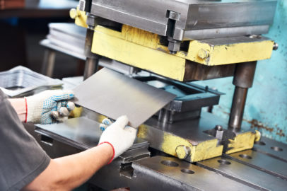
If your company designs sheet metal parts, it faces a series of unique challenges. Although parts are typically designed in their “formed” state, they begin as a flat plate. As a result, manufacturability becomes a critical aspect of every feature making up the finished part. Add to this the need to account also for material thickness, along with bend and corner relief, miter deformation features and critical dimensions (inside or outside).
When you take all of this into consideration, it becomes obvious that you need a highly specialized set of tools if you want to achieve real productivity and quality gains from design through manufacturing.
Sheet metal design in focus
Essential functions for sheet metal design software
Easy transform 2D into 3D
To speed the development process, you should be able to drag 2D sketches directly into a 3D model, dragging these elements into new features, as well as enable them to modify existing parts. Regions should be automatically be created from imported drawings.
State of the art functionalities
Specialized sheet metal design capabilities, such as dimples and beads, using sketches and engineering parameters, without having to regenerate unrelated geometry or downstream operations, are a must. In addition, you should be able to “wrap” sheet metal around a solid part.
Seamless data import
Import sheet metal model files and convert them to usable parts where edits can then be made. Your software should recognize key parameters on imported parts, such as thickness and bends. Higher usability arises from tools that allow synchronous modelling.
Embedded design validation
Unmatched model validation e.g. FEM analysis help to ensure manufacturability and reduce the need for physical prototypes. Useful are also features that automatically measure parameters, like the distance between bends, or calculate costs.
Ready for NC
For manufacturing purposes, your flat patterns should always show the most efficient cut sheet size. Bend tables should be stored within 3D parts to allow the bend order to be documented, used on drawings, and exported to help program CNC machines.
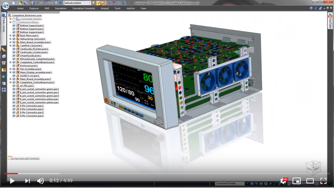
Find out how Solid Edge sheet metal design capabilities can help you to speed your design process
Download our Solid Edge sheet metal design whitepaper!