CAM tool specialist captures a competitive advantage using 3D design platform
CAM tool specialist captures a competitive advantage using 3D design platform
Case Study
CAM tool specialist captures a competitive advantage using 3D design platform with integrated support for 5-axis machining
The Te-Shin Cam
Using Solid Edge with synchronous technology and the 5-axis machining functionality of CAM Express, The Te-Shin Cam significantly improves its ability to meet its customers’ needs
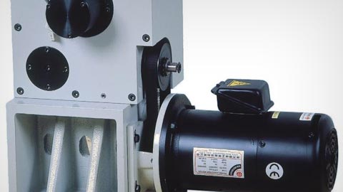
Critical CAM components
Established in 1980, The Te-shin Cam Co., Ltd. (Te-Shin) is devoted to the design and production of equipment related to computer-aided manufacturing (CAM). Its product line includes critical components, such as automatic tool changers (ATCs) and intervallic cutters.
Te-Shin boasts a large production capacity for this equipment, with a monthly output of up to 3,500 tool changers. It has become a leading industrial supplier of precision machinery in its region, and accounts for 85 percent of the Taiwanese market in its segment. The company’s intervallic cutter features high quality and an excellent cost-performance ratio, and sells for half the price of products imported from Japan.
In recent years, to meet the requirements of high-end, high-precision industries, Te-Shin invested in professional equipment for machining and grinding and adopted an advanced research and development (R&D) process based on 3D design. However, because the previous computer-aided design (CAD) system – one of the industry’s leading technologies – used a traditional modeling approach, the company found it difficult to deal with customers’ design changes in real time. This led to a search for a better solution, one that would deliver integrated design, manufacturing and data management functionality to enhance the company’s competitive edge.
Easy to learn and use
After careful assessment, Te-Shin adopted Solid Edge® software from Siemens Digital Industries Software for the drafting and design of all new tool changers. Designers find the new software to be easy to learn and use compared with its prior system, which involved complicated instructions and objects interrelated in a hierarchy. Designers found that system dull and time-consuming to use.
With Solid Edge, users can import the company’s legacy CAD drawings and manage those files, along with native models created using Solid Edge, thus reducing design and modification time, and decreasing miscommunication between design and manufacturing.
“In the past, in considering whether to adopt 3D design for new product development, our colleagues took the product lifecycle and timeliness into consideration,” explains Peirong. “But the ease of use of Solid Edge, along with the cutting-edge synchronous technology, enables us to use both 2D and 3D data effectively, which furthers the full acceptance and implementation of this new-generation, 3D design system.”
The new system was first used to provide 3D exploded views as required by customers for the purpose of including specifications in maintenance manuals. According to Peirong, “When using the previous 3D software, it normally required three days to draft an exploded view. Using Solid Edge, this is done in one day. Modifying a 3D model is as simple as modifying 2D drawings. We save valuable time.”
In addition, the adoption of synchronous technology means that design data can be updated quickly, which is an important benefit. “The synchronous modeling function allows us to update the change to the assembly drawing as we are changing the part drawing,” says Peirong. “This synchronous update capability effectively eliminates the consequence of changing the part drawing only and leaving the assembly drawing unchanged, which consequently might lead to errors in the subsequent operations.”